In short
CAN frames carry no sender address. Map IDs to ECUs by disconnecting one ECU at a time, by start-up order, by reading identification over UDS, or by clock drift: every ECU's crystal runs slightly fast or slow, and all periodic IDs from one ECU share that error.
Best for: Engineers reverse engineering a vehicle network, building a DBC from scratch, or checking which node sends unexpected traffic
A CAN frame says what it is, through its ID, but not who sent it. On a bus with a dozen ECUs and a hundred IDs, that makes a DBC hard to build: you know 0x1A0 carries wheel speeds, but is it the ABS module or the gateway forwarding it? You need the sender to name messages correctly, to know which ECU to query with diagnostics, and to spot a node that should not be there.
Five methods
| Method | What you need | What it tells you |
|---|---|---|
| 1. The DBC's transmitter field | A DBC for a related vehicle | Sender per message, if the DBC fits |
| 2. Disconnect one ECU | Access to fuses or connectors | IDs that disappear belong to that ECU |
| 3. Start-up order | A log from wake-up | IDs that start together come from one ECU |
| 4. Diagnostic identification | UDS access | Which physical ECU answers, with part numbers |
| 5. Clock drift | A long log with good timestamps | Groups of IDs that share one sender's clock |
Combine them. Each one is cheap on its own and they confirm each other.
1. Start from any DBC you have
Every message in a DBC has a transmitter: BO_ 416 ESP_Speed: 8 ESP says ECU ESP sends ID 0x1A0. A DBC for a sister model or an open-source DBC from opendbc gives you a hypothesis to test with the other methods.
2. Disconnect one ECU at a time
With the vehicle parked and the ignition on, record the bus, pull the fuse or connector of one ECU, and record again. IDs that vanish were sent by that ECU. IDs whose content changes, for example to error values or substitute values, are received by it, or by ECUs that react to its absence. Restore the ECU before moving on. Expect new DTCs in other ECUs; read and clear them afterwards.
This is the most reliable method, and the slowest. It also needs care: some ECUs, such as the gateway or the body controller, take other functions down with them.
3. Start-up order
ECUs boot at different speeds. Record from before the ignition turns on, then list the first appearance of each ID. IDs that start within a few milliseconds of each other, after the same pause, often come from one ECU's first transmit cycle. On networks with network management messages, each node sends its own, usually in a dedicated ID range, which helps you count the nodes.
4. Ask the ECUs
Every diagnosable ECU has its own diagnostic request and response IDs. A TesterPresent sweep finds them, and reading the identification DIDs (F187 part number, F18A supplier, F190 VIN) tells you what each one is. The UDS DID scanning guide has the code. That gives you a list of physical ECUs to map the application IDs onto.
5. Fingerprint the sender by its clock
Every ECU times its periodic messages from its own crystal or oscillator. No two run at exactly the same rate: one may be 80 parts per million fast, another 50 ppm slow. That error is the same for every message the ECU sends, so a 10 ms message and a 100 ms message from the same ECU drift by the same ppm. Measure the real period of each ID over a long log, and IDs from one ECU line up.
Research has used this idea for years. CANvas (USENIX Security 2019) identifies transmitting ECUs by tracking clock offsets between pairs of messages, and identifies receiving ECUs by briefly isolating one ECU at a time; its authors mapped real vehicles in under an hour.
This function fits a straight line through each ID's timestamps. The slope is the measured period; its deviation from the nominal period, in ppm, is the clock error:
import statistics
from collections import defaultdict


def timestamps(path):
    times = defaultdict(list)
    for line in open(path):
        stamp, _, frame = line.split()
        times[int(frame.split("#")[0], 16)].append(float(stamp.strip("()")))
    return times


def clock_drift(times):
    """Per CAN ID: nominal period and how far the measured period deviates from it, in ppm."""
    result = {}
    for can_id, stamps in sorted(times.items()):
        if len(stamps) < 100:
            continue
        rough = statistics.median(b - a for a, b in zip(stamps, stamps[1:]))
        index = [round((t - stamps[0]) / rough) for t in stamps]  # frame number, tolerant of lost frames
        period, _ = statistics.linear_regression(index, stamps)
        nominal = round(period, 3)  # assume periods are whole milliseconds
        result[can_id] = (nominal, (period / nominal - 1) * 1e6)
    return result


drift = clock_drift(timestamps("bus.log"))
for can_id, (nominal, ppm) in drift.items():
    print(f"0x{can_id:03X}  period {nominal * 1000:5.0f} ms  clock {ppm:+7.1f} ppm")
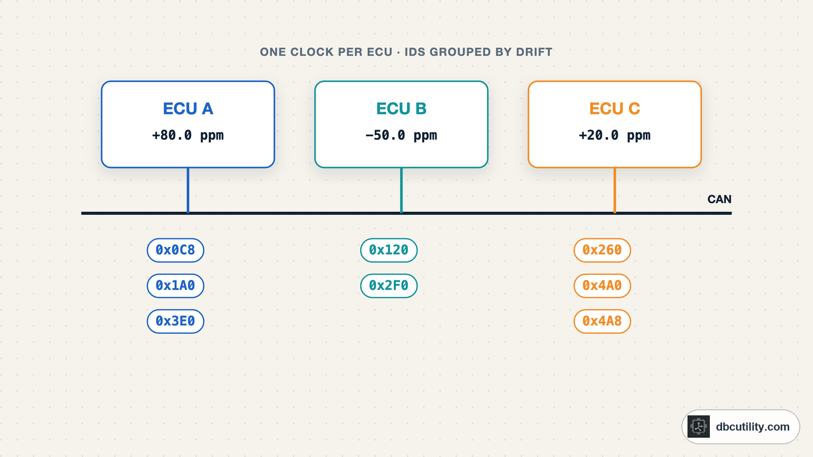
Output for a 60-second test log with three ECUs whose clocks run at +80, −50 and +20 ppm (make_log.py generates it as bus.log):
0x0C8  period    10 ms  clock   +80.0 ppm
0x120  period    20 ms  clock   -50.1 ppm
0x1A0  period    20 ms  clock   +80.0 ppm
0x260  period    20 ms  clock   +20.0 ppm
0x2F0  period    50 ms  clock   -50.0 ppm
0x3E0  period   100 ms  clock   +80.0 ppm
0x4A0  period   100 ms  clock   +20.1 ppm
0x4A8  period   100 ms  clock   +20.1 ppm
Then group IDs with the same drift:
def group_by_clock(drift, tolerance_ppm=5):
    """IDs whose clocks run at the same rate are probably sent by the same ECU."""
    groups = []
    for can_id, (_, ppm) in sorted(drift.items(), key=lambda item: item[1][1]):
        if groups and abs(ppm - groups[-1][0]) <= tolerance_ppm:
            groups[-1][1].append(can_id)
        else:
            groups.append((ppm, [can_id]))
    return groups


for ppm, ids in group_by_clock(drift):
    print(f"{ppm:+7.1f} ppm: " + ", ".join(f"0x{i:03X}" for i in sorted(ids)))
Output:
  -50.1 ppm: 0x120, 0x2F0
+20.0 ppm: 0x260, 0x4A0, 0x4A8
+80.0 ppm: 0x0C8, 0x1A0, 0x3E0
Three groups, three ECUs, matching how the log was generated, although every frame had 40 µs of random timing jitter. A one-minute log is enough because the regression averages the jitter over thousands of frames.
Things that affect the result on a real bus:
- The logger's clock shifts every ID by the same amount. The absolute ppm values are then off, but the groups stay intact.
- Timestamps taken in hardware by the CAN interface are better than software timestamps. With software timestamps, log longer.
- Event-driven IDs have no period, so they cannot be fingerprinted this way. Use methods 2 and 3 for them.
- Gateways forward messages from other buses. A forwarded ID carries the gateway's timing, not the original sender's.
- Temperature changes oscillator rates slowly. Compare IDs within one log, not across logs from different days.
Writing it down
Record the sender in your DBC as the message's transmitter, and list the ECUs in its BU_ line. Name ECUs by function, such as ABS, BCM or GW, once diagnostics or part numbers confirm what they are. A DBC with correct transmitters is what lets a restbus simulation stop one ECU's messages and replace them with your own, which is where testing starts.
Frequently asked questions
How do I know which ECU sends a CAN message?
CAN frames have no sender field. Disconnect one ECU at a time and see which IDs disappear, compare start-up order, read diagnostic identification, or group periodic IDs by their clock drift. A DBC's transmitter field gives the answer if you have one.
Can two ECUs send the same CAN ID?
They should not in normal operation, because two nodes sending the same ID with different data at the same moment cause bit errors. A gateway forwarding a message from another bus is a common reason an ID seems to have two sources.
What is CAN clock skew fingerprinting?
Each ECU's oscillator runs at a slightly different rate, so its periodic messages drift by a characteristic number of parts per million. Measuring the period of each ID precisely and grouping IDs with equal drift reveals which IDs share a sender.
How long a log do I need for clock-drift mapping?
On the test log above, one minute was enough to separate ECUs whose clocks differ by 60 ppm. Real buses with software timestamps, gateways and temperature changes may need longer logs. Check that the groups stay the same when you split the log in two halves.
References
DBC Utility
One desktop app for DBC files and CAN recordings.
One-time $34 · Windows & Linux · Files stay on your computer