In short
A CAN bit is split into time quanta. Bitrate = clock / (prescaler × time quanta per bit), and the sample point sits after Sync_Seg + Prop_Seg + Phase_Seg1. Pick the prescaler and segments that hit the exact bitrate with the sample point your network uses.
Best for: Embedded engineers bringing up a CAN controller, and anyone whose node sends error frames at a bitrate that should work
Two CAN nodes can both be set to 500 kbit/s and still not work together. The bitrate only says how long a bit is. The bit timing says where inside that bit each node reads the bus level. If one node reads too late, or its clock drifts too far, you get error frames that come and go with temperature and cable length.
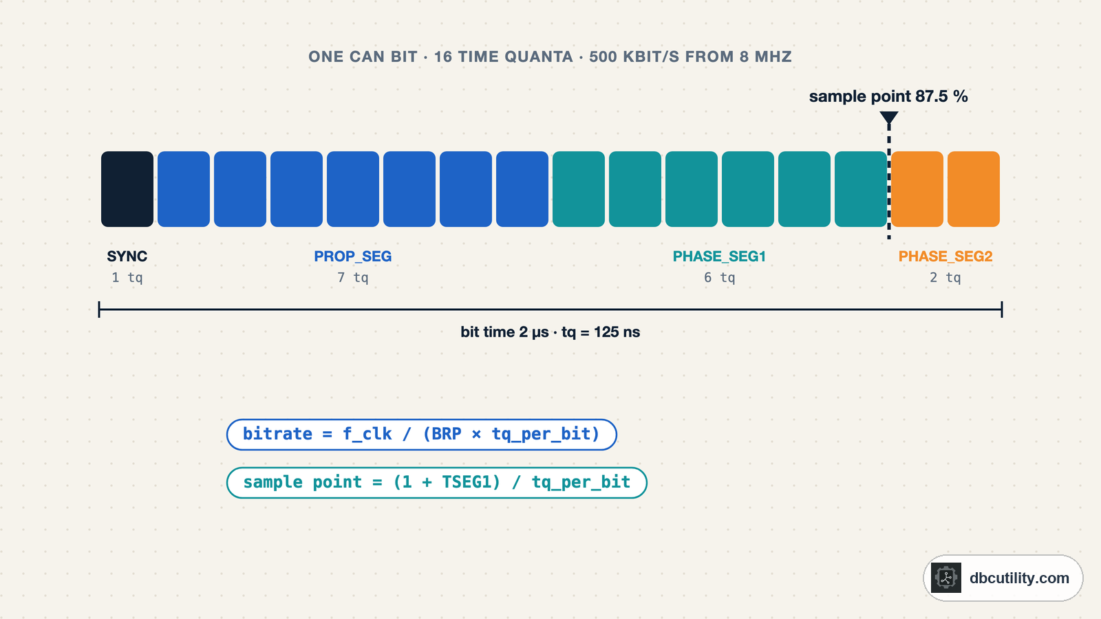
Here is a complete setting for 500 kbit/s from an 8 MHz CAN clock:
prescaler        1     -> 1 time quantum = 1 / 8 MHz = 125 ns
time quanta      16    -> 16 × 125 ns = 2 µs per bit = 500 kbit/s
Sync_Seg         1 tq
TSEG1            13 tq (Prop_Seg + Phase_Seg1)
TSEG2            2 tq  (Phase_Seg2)
sample point     (1 + 13) / 16 = 87.5 %
SJW              2 tq
The rest of this guide explains where each number comes from and how to calculate it for your clock.
What a CAN bit is made of
The CAN controller divides each bit into small, equal steps called time quanta (tq). The length of one time quantum comes from the controller clock and the baud rate prescaler (BRP):
tq = prescaler / f_clockThe CAN specification splits the bit into four segments. The minimum ranges every CAN controller must support, from Bosch's bit timing paper:
| Segment | Length | Job |
|---|---|---|
| Sync_Seg | 1 tq, fixed | Where the edges of the bus level are expected |
| Prop_Seg | 1–8 tq | Covers the delay of the signal on the cable and through the transceivers |
| Phase_Seg1 | 1–8 tq | Can be lengthened to resynchronise to a late edge |
| Phase_Seg2 | 1–8 tq | Can be shortened to resynchronise to an early edge |
| SJW | 1–4 tq | How far one resynchronisation may move the sample point; not longer than either phase segment |
The bus level is read at the sample point, the boundary between Phase_Seg1 and Phase_Seg2:
|Sync| Prop_Seg      | Phase_Seg1   | Phase_Seg2 |
| 1  |  1 .. 8 tq    |  1 .. 8 tq   |  1 .. 8 tq |
                                    ^
                              sample point
A bit can have 8 to 25 time quanta. Most controllers do not let you set Prop_Seg and Phase_Seg1 separately. They combine them into TSEG1, and call Phase_Seg2 TSEG2.
The two formulas
Everything in CAN bit timing follows from two lines:
bitrate      = f_clock / (prescaler × tq_per_bit)
tq_per_bit   = 1 + TSEG1 + TSEG2
sample point = (1 + TSEG1) / tq_per_bit
Work it backwards for 250 kbit/s from a 16 MHz clock:
- Clock cycles per bit: 16 000 000 / 250 000 = 64.
- Find a prescaler that leaves 8 to 25 time quanta: 64 / 4 = 16 tq. Prescaler 4.
- For an 87.5 % sample point: 16 × 0.875 = 14 tq before the sample point. TSEG1 = 14 − 1 = 13.
- TSEG2 = 16 − 1 − 13 = 2.
- SJW can be at most the smaller phase segment, so SJW = 2.
The prescaler must divide the clock exactly. If f_clock / (prescaler × bitrate) is not a whole number, the bitrate is wrong, and a small error adds up over the 10 or more bits between resynchronising edges.
Registers store the value minus one
The numbers above are functional values. Most CAN controllers store TSEG1, TSEG2, SJW and the prescaler as one less than that value, so a 2-bit field can hold SJW 1 to 4. Bosch describes this layout for its controllers, and Kvaser's bit timing page says the same for the SJA1000.
| Setting | Functional value | Written to the register |
|---|---|---|
| Prescaler | 4 | 3 |
| TSEG1 | 13 | 12 |
| TSEG2 | 2 | 1 |
| SJW | 2 | 1 |
This is the most common reason a configuration copied from another project runs at the wrong bitrate. Check your controller's reference manual for each field, and never mix register values from one microcontroller family into the formula for another.
Calculate it for any clock in Python
This function lists every exact setting for a clock and bitrate, closest sample point first. It keeps TSEG1 within 2–16 tq and TSEG2 within 2–8 tq, the Bosch minimum ranges, and it never makes Phase_Seg2 shorter than 2 tq, since Bosch puts the controller's information processing time at 0 to 2 tq.
def bit_timings(clock_hz, bitrate, sample_point=0.875, max_tseg1=16, max_tseg2=8):
    """List every (prescaler, TSEG1, TSEG2) that gives the exact bitrate, closest sample point first."""
    results = []
    for prescaler in range(1, 1025):
        tq_per_bit, remainder = divmod(clock_hz, prescaler * bitrate)
        if remainder or not 8 <= tq_per_bit <= 25:
            continue
        for tseg2 in range(2, max_tseg2 + 1):
            tseg1 = tq_per_bit - 1 - tseg2
            if 2 <= tseg1 <= max_tseg1:
                actual = (1 + tseg1) / tq_per_bit
                results.append({
                    "prescaler": prescaler,
                    "tq_per_bit": tq_per_bit,
                    "tseg1": tseg1,
                    "tseg2": tseg2,
                    "sjw": min(4, tseg2),
                    "sample_point": round(actual * 100, 1),
                    "error": round(abs(actual - sample_point) * 100, 1),
                })
    return sorted(results, key=lambda r: (r["error"], -r["tq_per_bit"]))


best = bit_timings(8_000_000, 500_000)[0]
print(best)
Output:
{'prescaler': 1, 'tq_per_bit': 16, 'tseg1': 13, 'tseg2': 2, 'sjw': 2, 'sample_point': 87.5, 'error': 0.0}Pass a different sample_point if your network uses another value, for example bit_timings(16_000_000, 500_000, sample_point=0.8).
Settings for common clocks
These rows come from running the function above with an 87.5 % target. Each cell reads prescaler / tq per bit / TSEG1+TSEG2 / sample point.
| Clock | 125 kbit/s | 250 kbit/s | 500 kbit/s | 1 Mbit/s |
|---|---|---|---|---|
| 8 MHz | 4 / 16 tq / 13+2 / 87.5 % | 2 / 16 tq / 13+2 / 87.5 % | 1 / 16 tq / 13+2 / 87.5 % | 1 / 8 tq / 5+2 / 75.0 % |
| 16 MHz | 8 / 16 tq / 13+2 / 87.5 % | 4 / 16 tq / 13+2 / 87.5 % | 2 / 16 tq / 13+2 / 87.5 % | 1 / 16 tq / 13+2 / 87.5 % |
| 20 MHz | 10 / 16 tq / 13+2 / 87.5 % | 5 / 16 tq / 13+2 / 87.5 % | 2 / 20 tq / 16+3 / 85.0 % | 1 / 20 tq / 16+3 / 85.0 % |
| 24 MHz | 12 / 16 tq / 13+2 / 87.5 % | 6 / 16 tq / 13+2 / 87.5 % | 3 / 16 tq / 13+2 / 87.5 % | 2 / 12 tq / 9+2 / 83.3 % |
| 40 MHz | 20 / 16 tq / 13+2 / 87.5 % | 10 / 16 tq / 13+2 / 87.5 % | 5 / 16 tq / 13+2 / 87.5 % | 2 / 20 tq / 16+3 / 85.0 % |
| 80 MHz | 40 / 16 tq / 13+2 / 87.5 % | 20 / 16 tq / 13+2 / 87.5 % | 10 / 16 tq / 13+2 / 87.5 % | 5 / 16 tq / 13+2 / 87.5 % |
Two cells show the limits:
- 8 MHz at 1 Mbit/s has only 8 cycles per bit, so there are 8 time quanta. With Phase_Seg2 at 2 tq, the latest sample point is 6/8 = 75 %.
- 24 MHz at 1 Mbit/s could use 24 tq, but TSEG1 tops out at 16, which puts the sample point at 17/24 = 70.8 %. Prescaler 2 with 12 tq reaches 83.3 %.
What the sample point costs and buys
A later sample point leaves more time for the signal to cross the bus. An earlier one leaves more room for clock error. Bosch gives the oscillator tolerance df a configuration can handle as two conditions, both of which must hold (all values in tq):
I:   df ≤ min(Phase_Seg1, Phase_Seg2) / (2 × (13 × bit_time − Phase_Seg2))
II:  df ≤ SJW / (20 × bit_time)
This function applies both:
def oscillator_tolerance(phase_seg1, phase_seg2, sjw, tq_per_bit):
    """Largest clock tolerance (as a fraction) allowed by Bosch's two bit timing conditions."""
    condition_1 = min(phase_seg1, phase_seg2) / (2 * (13 * tq_per_bit - phase_seg2))
    condition_2 = sjw / (20 * tq_per_bit)
    return min(condition_1, condition_2)


for name, segments in {
    "16 tq, sample point 87.5 %": (6, 2, 2, 16),
    "16 tq, sample point 75 %": (4, 4, 4, 16),
    "10 tq, Bosch example": (4, 4, 4, 10),
}.items():
    print(f"{name}: {oscillator_tolerance(*segments) * 100:.3f} %")
Output:
16 tq, sample point 87.5 %: 0.485 %
16 tq, sample point 75 %: 0.980 %
10 tq, Bosch example: 1.587 %
The first two rows use Prop_Seg = 7 tq. Moving the sample point from 87.5 % to 75 % doubles the clock error the node can absorb, but takes 2 tq away from the time the signal has to arrive. The last row is the configuration Bosch names as the most tolerant: Prop_Seg 1, both phase segments and SJW 4. Bosch notes that its short Prop_Seg only suits rates up to 125 kbit/s on a 40 m bus.
That trade-off is why networks fix one sample point in their specification. Use the value from your OEM, CANopen or J1939 network documents rather than picking your own.
How long Prop_Seg has to be
When two nodes arbitrate, a dominant bit from the far node has to reach the first node before its Phase_Seg1 starts. Otherwise the first node can read recessive, see a bit error, and destroy the frame. Prop_Seg therefore has to cover the round trip: cable delay both ways plus the transmit and receive delays of both transceivers. A Prop_Seg that is too short only fails when the two most distant nodes arbitrate and their clocks sit at opposite ends of the tolerance range, so it shows up as rare, random error frames.
Set it on Linux with SocketCAN
On Linux you give the bitrate and sample point, and the kernel calculates the segments:
sudo ip link set can0 type can bitrate 500000 sample-point 0.875
sudo ip link set can0 up
ip -details link show can0
The details output lists the timing the kernel chose: tq in nanoseconds, then prop-seg, phase-seg1, phase-seg2 and sjw in time quanta. Check it with the formula:
bitrate = 1 000 000 000 / (tq × (1 + prop-seg + phase-seg1 + phase-seg2))If the requested sample point cannot be reached exactly, the kernel uses the closest one it can, so always read the result back.
CAN FD has two bit timings
A CAN FD frame is sent at the nominal (arbitration) bitrate, then switches to a faster data bitrate. Each phase has its own prescaler, segments and sample point, calculated with the same formulas. On Linux:
sudo ip link set can0 up type can bitrate 500000 sample-point 0.8 dbitrate 2000000 dsample-point 0.8 fd onAt data rates of a few Mbit/s, the delay through the transceiver becomes a large part of the bit, and a transmitter can no longer check its own bits at the normal sample point. CAN FD controllers solve this with transmitter delay compensation (TDC), which measures the delay and checks the transmitted bits at a secondary sample point. Leave TDC in its automatic mode unless your network specification says otherwise.
CAN FD controllers support far longer segments than the classical 8 to 25 tq. With an 80 MHz clock and prescaler 1, a 500 kbit/s nominal bit is 160 tq and a 2 Mbit/s data bit is 40 tq. CiA recommends 20, 40 or 80 MHz CAN clocks for CAN FD. The CAN FD guide covers the frame format.
When a node sends error frames
- Measure one bit on a scope. At 500 kbit/s it must be 2 µs. If it is 2.08 µs, the clock or prescaler is wrong.
- Check the clock source. Compare the accuracy in the oscillator's datasheet with the tolerance your timing allows, for example 0.485 % in the 87.5 % example above. Internal RC oscillators are much less accurate than crystals.
- Check minus-one fields. Compare what is written in the register with the functional value.
- Compare sample points. Read the sample point of every node on the bus and compare them with the network specification.
- Watch the error counters. The error frames and bus-off guide shows how to read them with SocketCAN.
Frequently asked questions
What is a good CAN sample point?
The one your network specification gives. A later sample point allows longer buses, an earlier one allows more clock error. The examples in this guide target 87.5 %.
What is a time quantum in CAN?
The smallest unit of time inside a CAN bit. It equals the prescaler divided by the CAN clock frequency, so with an 8 MHz clock and prescaler 1, one time quantum is 125 ns. A classical CAN bit has 8 to 25 of them.
Why do I get error frames when the bitrate is right?
The bit length can be right while the sample point, SJW or clock accuracy are wrong. Check the segment values, the minus-one encoding in the registers, and the clock source before looking at wiring.
Can I run 1 Mbit/s CAN from an 8 MHz clock?
Yes, with prescaler 1 and 8 time quanta per bit. The latest sample point is 75 %, and each time quantum is 125 ns, so there is little room for adjustment. A 16 MHz or faster clock gives finer steps.
References
DBC Utility
One desktop app for DBC files and CAN recordings.
One-time $34 · Windows & Linux · Files stay on your computer