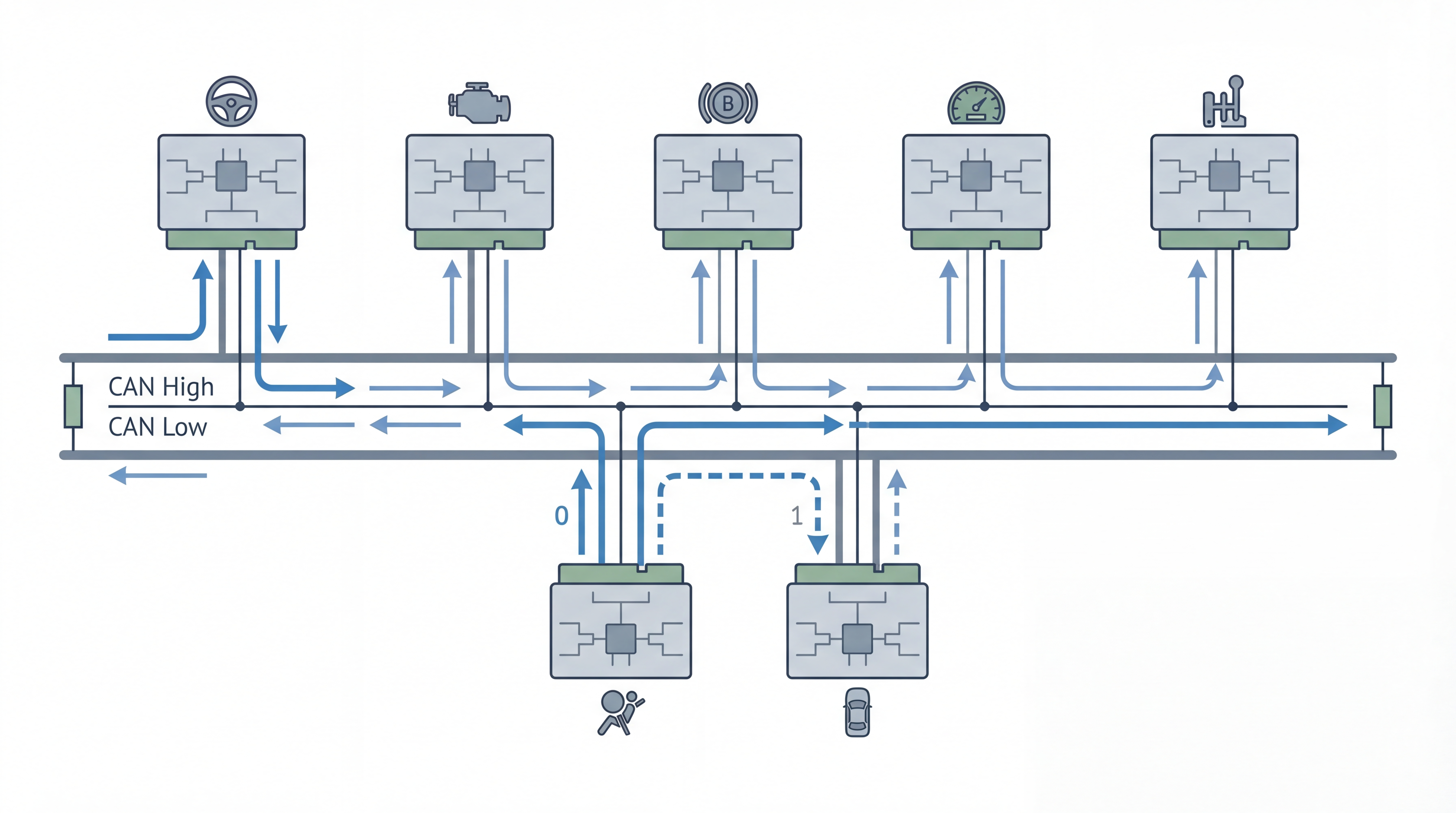
CAN bus in one sentence
CAN bus is a way for small computers to talk to each other over the same pair of wires.
CAN stands for Controller Area Network. It is common in cars, trucks, machines, robots, medical equipment, and factory systems. The small computers connected to the network are often called controllers, nodes, or ECUs.
Think of CAN like a group chat for controllers. Every controller can hear each message. Each one decides whether the message is useful to it.
Why CAN bus is used
Without CAN, every controller would need separate wires to every other controller. A vehicle with dozens of ECUs would quickly need a large, heavy wiring harness.
CAN lets those controllers share one network. It gives engineers:
- fewer wires
- reliable communication in electrically noisy places
- message priority
- built-in error checking
- support for many controllers on one bus
CAN is not designed for video or large files. It is designed for small, frequent values such as engine speed, pedal position, temperature, switch status, and fault information.
What the CAN wires do
A typical high-speed CAN bus uses two signal wires:
CAN_HCAN_L
The receiver looks at the voltage difference between the two wires. This differential signal helps CAN work reliably around motors, ignition systems, and other sources of electrical noise.
The bus normally has a 120 ohm terminating resistor at each physical end. With the power off, engineers often measure about 60 ohms between CAN_H and CAN_L because the two 120 ohm resistors appear in parallel.
What a CAN message looks like
A CAN message is usually called a frame. The most important parts for a beginner are:
| Part | Meaning |
|---|---|
| CAN ID | Tells receivers what the message represents and gives it a priority |
| DLC | Says how many data bytes are present |
| Data | Contains the actual values |
| CRC and checks | Help receivers detect transmission errors |
A raw frame may look like this:
ID: 0x123 DLC: 8 Data: 10 27 00 00 01 00 00 00The frame does not automatically say that 10 27 means motor speed. Your team needs a message definition for that. A DBC file is one common way to store those definitions.
CAN IDs are labels, not device addresses
On many networks, data is sent directly from one address to another. CAN usually works differently.
The CAN ID describes the message. For example:
0x100 -> vehicle speed
0x120 -> engine speed
0x220 -> steering angle
Every ECU sees the frame. The dashboard may use vehicle speed, while the radio ignores it. This is why one CAN frame can be useful to several controllers at the same time.
Classical CAN supports:
- 11-bit standard IDs
- 29-bit extended IDs
- up to 8 data bytes in one frame
CAN FD keeps the same basic idea but allows a larger payload and a faster data phase.
What happens when two ECUs transmit together
CAN uses arbitration. If two ECUs start sending at the same time, the frame with the higher priority continues. The other ECU stops and tries again when the bus is free.
Lower numeric CAN IDs normally have higher priority. For example, 0x100 wins over 0x300 if both start at the same time.
The useful part is that the winning frame is not destroyed. CAN avoids the random collision behavior seen in some older shared networks.
A simple real-world example
Imagine an engine ECU sends this frame every 10 milliseconds:
ID: 0x120 Data: 40 1F 00 00 00 00 00 00The DBC file may define the first two bytes as engine speed with a scale of 0.25 rpm per bit.
raw value = 0x1F40 = 8000
engine speed = 8000 x 0.25 = 2000 rpm
The instrument cluster can now display 2000 rpm. A logger can record the same value. A transmission ECU can use it for control. The engine ECU only had to send one frame.
What you need to work with CAN
For a basic bench setup, you need:
- Two or more CAN nodes, or one node and a simulator
- A CAN adapter for your computer
- Correct wiring and termination
- The same bitrate on every node
- Software such as SocketCAN, python-can, CANalyzer, or another CAN tool
- A DBC file if you want names and engineering values instead of raw bytes
Start in listen-only mode when you connect to an unknown network. Sending the wrong frame can change the behavior of a real system.
CAN bus, CAN FD, J1939, and UDS
These terms are related, but they are not the same:
| Term | Simple meaning |
|---|---|
| CAN | The basic network and frame format |
| CAN FD | A newer CAN format with more data and a faster data phase |
| J1939 | A higher-level protocol that uses 29-bit CAN IDs, common in heavy vehicles |
| UDS | A diagnostic protocol often carried over CAN using ISO-TP |
| DBC | A file that explains how CAN frame data is divided into signals |
The simple summary
CAN is a shared, reliable network for short control messages. Controllers send frames with IDs, every node can hear them, and each node uses only the messages it needs. Once you understand IDs, data bytes, bitrate, and termination, you have the foundation for CAN tools, DBC files, J1939, diagnostics, and code examples.