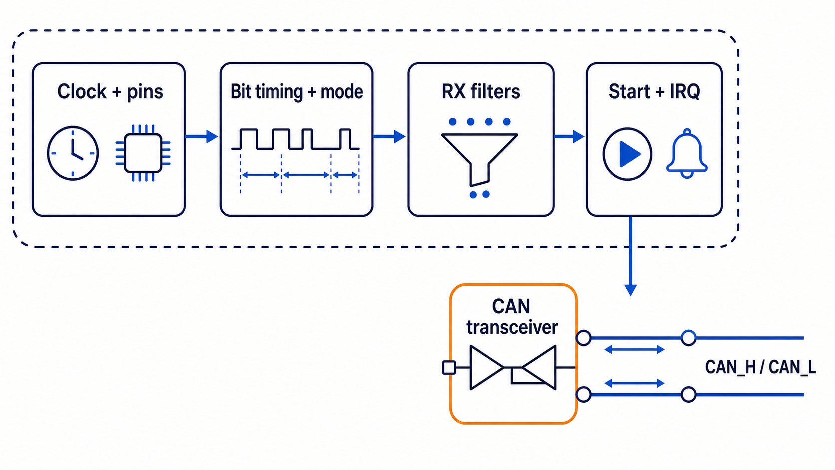
What “enable CAN” really means
Adding CAN to firmware is not one function call. The complete path is:
application code
-> CAN peripheral
-> TX and RX pins
-> CAN transceiver
-> CAN_H and CAN_L
If any part is missing, the code may run without a valid frame appearing on the bus.
The seven setup steps
Most microcontrollers need the same basic sequence:
- Enable the peripheral clock.
- Configure the CAN TX and RX pins.
- Configure CAN bit timing.
- Choose normal, loopback, or silent mode.
- Configure receive filters.
- Start the CAN peripheral.
- Enable receive and error interrupts if the application uses them.
You also need an external CAN transceiver unless it is already built into the hardware.
Start with the hardware
The MCU CAN peripheral produces logic-level TX and RX signals. A transceiver converts those signals to CAN_H and CAN_L.
Check:
- transceiver supply voltage
- transceiver standby or enable pin
- TX and RX pin routing
- CAN_H and CAN_L wiring
- common ground requirements
- bus termination
A disabled transceiver can make correct firmware look broken.
Calculate the CAN bitrate
CAN bit timing is built from time quanta. A common simplified relationship is:
bitrate = CAN peripheral clock / (prescaler x time quanta per bit)The time quanta per bit include the synchronization segment, time segment 1, and time segment 2.
Do not copy timing values from a project with a different peripheral clock. Use the MCU reference manual or vendor timing calculator. Confirm the sample point and oscillator tolerance for your network.
Vendor-neutral initialization structure
The exact function names differ, but the code usually follows this shape:
bool can_init(void)
{
    can_enable_clock();
    can_configure_pins();

    can_config_t config = {
        .bitrate = 500000,
        .mode = CAN_MODE_NORMAL,
        .auto_retransmit = true,
    };

    if (!can_peripheral_init(&config)) {
        return false;
    }

    can_filter_t filter = {
        .id = 0x100,
        .mask = 0x700,
    };

    if (!can_set_filter(0, &filter)) {
        return false;
    }

    can_enable_rx_interrupt();
    return can_start();
}
This is a design pattern, not a library you can compile as-is. Replace the names with your MCU driver's API.
STM32 bxCAN HAL example
The following example assumes STM32CubeMX already generated hcan1, GPIO setup, peripheral clocks, and the bit timing. It shows the part engineers commonly miss: filters, start, notifications, and transmit.
#include "main.h"

extern CAN_HandleTypeDef hcan1;

static void CAN_Enable(void)
{
    CAN_FilterTypeDef filter = {0};

    /* Accept all standard and extended IDs into FIFO 0 for bring-up. */
    filter.FilterBank = 0;
    filter.FilterMode = CAN_FILTERMODE_IDMASK;
    filter.FilterScale = CAN_FILTERSCALE_32BIT;
    filter.FilterIdHigh = 0;
    filter.FilterIdLow = 0;
    filter.FilterMaskIdHigh = 0;
    filter.FilterMaskIdLow = 0;
    filter.FilterFIFOAssignment = CAN_RX_FIFO0;
    filter.FilterActivation = ENABLE;

    if (HAL_CAN_ConfigFilter(&hcan1, &filter) != HAL_OK) {
        Error_Handler();
    }

    if (HAL_CAN_Start(&hcan1) != HAL_OK) {
        Error_Handler();
    }

    if (HAL_CAN_ActivateNotification(
            &hcan1,
            CAN_IT_RX_FIFO0_MSG_PENDING | CAN_IT_BUSOFF | CAN_IT_ERROR) != HAL_OK) {
        Error_Handler();
    }
}
Send one frame:
static HAL_StatusTypeDef CAN_SendExample(void)
{
    CAN_TxHeaderTypeDef header = {0};
    uint8_t data[8] = {0x40, 0x1F, 0, 0, 0, 0, 0, 0};
    uint32_t mailbox;

    header.StdId = 0x123;
    header.IDE = CAN_ID_STD;
    header.RTR = CAN_RTR_DATA;
    header.DLC = 8;
    header.TransmitGlobalTime = DISABLE;

    return HAL_CAN_AddTxMessage(&hcan1, &header, data, &mailbox);
}
The STM32 FDCAN peripheral uses different types and functions. Use the driver that matches the actual MCU.
Receive frames without doing too much in the interrupt
void HAL_CAN_RxFifo0MsgPendingCallback(CAN_HandleTypeDef *hcan)
{
    CAN_RxHeaderTypeDef header;
    uint8_t data[8];

    if (HAL_CAN_GetRxMessage(hcan, CAN_RX_FIFO0, &header, data) == HAL_OK) {
        can_queue_push_from_isr(header.StdId, header.DLC, data);
    }
}
Keep the interrupt short. Copy the frame into a queue, then decode it in the application task.
Use loopback before a physical bus
Internal loopback is useful for checking peripheral configuration without depending on wiring or another node.
Test in this order:
- Internal loopback
- Two-node bench network
- Listen-only connection to the target
- Controlled transmit on the target network
Loopback does not prove the transceiver and physical bus are correct, but it separates software setup from wiring problems.
Why a single node may not transmit successfully
Normal CAN expects another active node to acknowledge a valid frame. If only one node is connected, it may repeatedly transmit, increase error counters, and eventually enter bus-off.
Use loopback for a one-controller test, or connect a second active CAN node with correct bitrate and termination.
Production checks
Before calling the CAN feature complete, handle:
- receive queue overflow
- transmit queue full
- error-active, error-passive, and bus-off states
- bus-off recovery policy
- message timeouts
- invalid DLC
- unexpected IDs
- startup and shutdown sequencing
- concurrency between interrupts and tasks
The simple summary
To enable CAN in embedded C, configure the complete hardware and software path. Set the correct bit timing, configure filters, start the peripheral, keep interrupts short, and verify the bus with a second node. A successful initialization return value does not by itself prove that CAN_H and CAN_L are working.