In short
E2E adds a counter and a CRC to safety-relevant data so the receiving software can detect corruption, loss, repetition and masquerading anywhere on the way, including in gateways. On classical CAN, Profiles 1 and 2 (and their successors 11 and 22) use an 8-bit CRC that also covers a Data ID that is never or only partly sent.
Best for: Engineers implementing, testing or reverse engineering safety-relevant CAN messages, and anyone writing DBC files for them
CAN frames already carry a 15-bit CRC. So why do safety-relevant messages carry a second one? Because the CAN CRC only protects one hop on one bus. It does not notice a gateway that copies the wrong signal into a frame, a software layer that sends yesterday's value, or a message from the wrong sender with the right ID. AUTOSAR's end-to-end (E2E) protection puts a counter and a CRC into the data itself, calculated by the sending software and checked by the receiving software, so faults anywhere in between are caught.
This guide uses the AUTOSAR E2E Protocol Specification, release R22-11. The AUTOSAR CAN stack guide shows where E2E sits in the software.
What E2E detects
Each mechanism covers different faults:
| Mechanism | Detects |
|---|---|
| Counter (sequence number) | Lost, repeated, delayed or out-of-order messages |
| CRC over the data | Corrupted data, from bit errors to wrong bytes copied by a gateway |
| Data ID inside the CRC | Masquerading: data from another message arriving under this message's ID |
| Timeout from the counter | A sender that stops |
The Data ID is the clever part. It is a number unique to each protected message, included in the CRC calculation but mostly not sent. A receiver that expects message A calculates the CRC with A's Data ID. If it gets message B's bytes by mistake, the CRC does not match, even if B's bytes are otherwise valid.
The profiles for classical CAN
| Profile 1 | Profile 2 | |
|---|---|---|
| CRC | 8 bits, polynomial 0x1D (CRC-8 SAE J1850), start and final XOR 0x00 | 8 bits, polynomial 0x2F (CRC-8H2F), start and final XOR 0xFF |
| Counter | 4 bits, counts 0 to 14 and skips 15 | 4 bits, counts 0 to 15 |
| Data ID | 16 bits, included in the CRC; four modes for how | 8 bits, taken from a list of 16 by the counter value |
| Default layout | CRC in byte 0, counter in the low nibble of byte 1 | CRC in byte 0, counter in the low nibble of byte 1 |
| Status in R22-11 | Legacy; new projects shall use Profile 11 | Legacy; new projects shall use Profile 22 |
Profiles 11 and 22 keep the same bus layout as 1 and 2, so a frame looks the same on the wire, but improve the behaviour of the protect and check functions. For reverse engineering and DBC work, 1 and 11, and 2 and 22, look identical.
Profile 1's Data ID modes
| Mode | What goes into the CRC |
|---|---|
| BOTH | Low byte and high byte of the Data ID |
| ALT | Low byte with even counter values, high byte with odd ones |
| LOW | Only the low byte; the high byte must be 0 |
| NIBBLE | Low byte and a zero byte; the Data ID's 4-bit high nibble is sent in the high nibble of byte 1 |
In every mode, the CRC is calculated first over the Data ID bytes and then over all data bytes except the CRC byte.
Profile 2's Data ID list
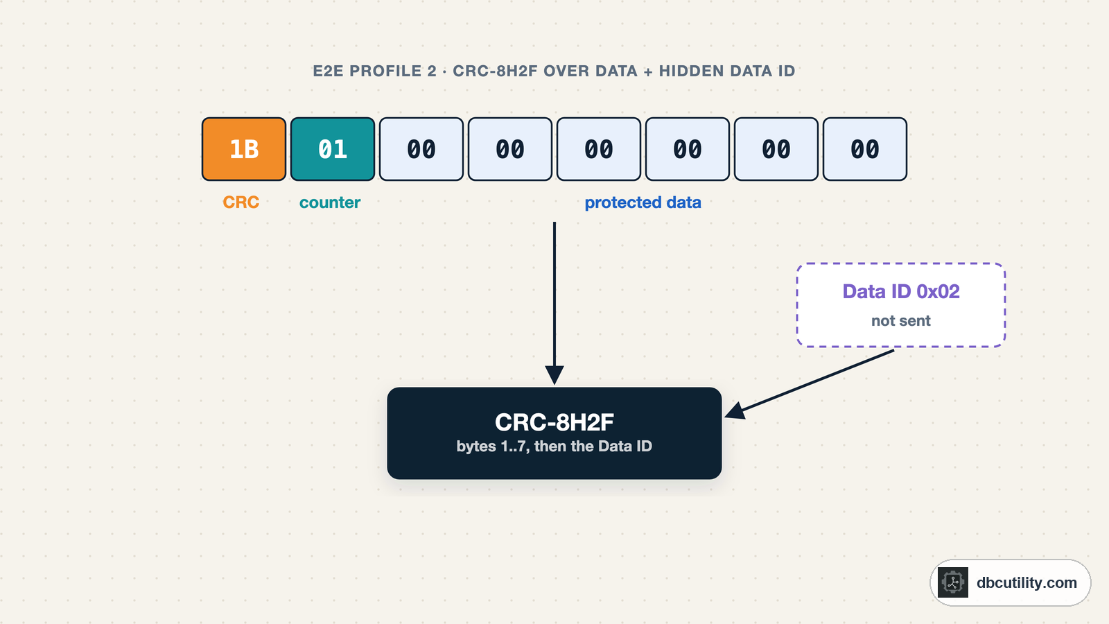
Profile 2 picks the Data ID for each frame from a list of 16 values, indexed by the counter. The same data therefore gets a different CRC for each counter value, and a receiver also detects a frame whose counter was corrupted. The CRC is calculated over bytes 1 to n−1 first and the Data ID last.
Profiles 1 and 2 in Python
The specification includes protect results for all-zero data, which make a good test for any implementation:
def crc8(data, poly, init, xor_out):
    crc = init
    for byte in data:
        crc ^= byte
        for _ in range(8):
            crc = ((crc << 1) ^ poly) & 0xFF if crc & 0x80 else (crc << 1) & 0xFF
    return crc ^ xor_out


def p01_protect(data, counter, data_id, mode="BOTH"):
    """E2E Profile 1 with the default layout: CRC in byte 0, counter in the low nibble of byte 1."""
    data = bytearray(data)
    data[1] = (data[1] & 0xF0) | (counter & 0x0F)
    if mode == "NIBBLE":  # high nibble of the Data ID's high byte is sent in byte 1
        data[1] = (data[1] & 0x0F) | ((data_id >> 8) & 0x0F) << 4
        id_bytes = bytes([data_id & 0xFF, 0x00])
    elif mode == "BOTH":
        id_bytes = bytes([data_id & 0xFF, data_id >> 8])
    elif mode == "ALT":  # low byte with even counters, high byte with odd counters
        id_bytes = bytes([data_id & 0xFF if counter % 2 == 0 else data_id >> 8])
    else:  # "LOW"
        id_bytes = bytes([data_id & 0xFF])
    data[0] = crc8(id_bytes + bytes(data[1:]), 0x1D, 0x00, 0x00)  # CRC-8 SAE J1850 polynomial, start/XOR 0
    return bytes(data)


def p02_protect(data, counter, data_id_list):
    """E2E Profile 2: counter in the low nibble of byte 1, CRC-8H2F over bytes 1.. and the Data ID."""
    data = bytearray(data)
    data[1] = (data[1] & 0xF0) | (counter & 0x0F)
    data[0] = crc8(bytes(data[1:]) + bytes([data_id_list[counter & 0x0F]]), 0x2F, 0xFF, 0xFF)
    return bytes(data)


zeros = bytes(8)
for mode in ("BOTH", "ALT", "LOW", "NIBBLE"):
    results = [p01_protect(zeros, counter, 0x123, mode)[:2].hex(" ") for counter in (0, 1)]
    print(f"Profile 1 {mode:<6} counter 0: {results[0]}   counter 1: {results[1]}")
data_ids = list(range(1, 17))
print("Profile 2 counters 1-4:", [p02_protect(zeros, c, data_ids)[:2].hex(" ") for c in range(1, 5)])
Output:
Profile 1 BOTH   counter 0: cc 00   counter 1: 91 01
Profile 1 ALT    counter 0: ce 00   counter 1: 02 01
Profile 1 LOW    counter 0: ce 00   counter 1: 93 01
Profile 1 NIBBLE counter 0: 2a 10   counter 1: 77 11
Profile 2 counters 1-4: ['1b 01', '98 02', '31 03', '0d 04']
Every value matches the example tables in the R22-11 specification: Data ID 0x123 for Profile 1, and Data ID list 0x01 to 0x10 for Profile 2.
What the receiver checks
The receiving side recalculates the CRC with the Data ID it expects, then compares the counter with the last valid one. Profile 2's check reports statuses such as OK, REPEATED, OKSOMELOST, WRONGSEQUENCE and WRONGCRC. A simplified version, without the specification's full initialisation and synchronisation state machine:
class P02Receiver:
    """Simplified Profile 2 check: CRC first, then the counter step since the last valid frame."""

    def __init__(self, data_id_list, max_delta_counter=1):
        self.data_id_list, self.max_delta, self.last = data_id_list, max_delta_counter, None

    def check(self, data):
        counter = data[1] & 0x0F
        expected = crc8(bytes(data[1:]) + bytes([self.data_id_list[counter]]), 0x2F, 0xFF, 0xFF)
        if data[0] != expected:
            return "WRONGCRC"
        if self.last is None:
            self.last = counter
            return "INITIAL"
        delta = (counter - self.last) % 16
        self.last = counter
        if delta == 0:
            return "REPEATED"
        if delta == 1:
            return "OK"
        return "OKSOMELOST" if delta <= self.max_delta else "WRONGSEQUENCE"


sent = [p02_protect(bytes([0, 0, 0x88, 0x13, 0, 0, 0, 0]), c, data_ids) for c in range(8)]
corrupted = bytearray(sent[4])
corrupted[2] ^= 0x01  # one flipped bit in the speed signal
received = [sent[0], sent[1], sent[1], sent[2], bytes(corrupted), sent[5], sent[7]]
receiver = P02Receiver(data_ids, max_delta_counter=2)
print([receiver.check(frame) for frame in received])
Output:
['INITIAL', 'OK', 'REPEATED', 'OK', 'WRONGCRC', 'WRONGSEQUENCE', 'OKSOMELOST']Frame by frame: the first frame initialises the check; a repeated counter is REPEATED; a single flipped bit in the speed value is WRONGCRC; a jump of three counter values is more than the allowed two, so WRONGSEQUENCE; a jump of two is accepted as OKSOMELOST. What the application does with each status, for example using a substitute value after a number of failures, is defined by the ECU's safety requirements.
Larger profiles for CAN FD and Ethernet
An 8-bit CRC and a 4-bit counter are sized for 8-byte frames. For longer data, the specification defines larger profiles, for example:
| Profile | CRC | Counter | Data ID | Length field |
|---|---|---|---|---|
| 4 | 32 bits, polynomial 0xF4ACFB13 | 16 bits | 32 bits | 16 bits |
| 5 | 16 bits, polynomial 0x1021 | 8 bits | 16 bits, not sent | none |
| 7 | 64 bits, polynomial 0x42F0E1EBA9EA3693 | 32 bits | 32 bits | 32 bits |
These protect larger messages such as SOME/IP payloads and CAN FD frames, where an E2E header can also sit inside the payload at a configurable offset.
E2E in a DBC
A DBC has no standard way to describe E2E. In practice, the CRC and counter appear as ordinary signals, and the profile, Data ID and layout go into comments or manufacturer-specific attributes. When you write or review such a DBC:
- Name the fields clearly, for example
ESP_Speed_CRCandESP_Speed_Counter. - Record the profile and Data ID in the message comment.
- Make sure every tool that sends the message, such as a restbus simulation, calculates the fields per frame, as in the restbus guide.
If you meet E2E-protected messages without documentation, the counters and CRC guide shows how to recover a working CRC from captured frames without knowing the Data ID.
Frequently asked questions
What is AUTOSAR E2E protection?
A set of profiles that add a counter, a CRC and an implicit Data ID to safety-relevant data. The sending software calculates them and the receiving software checks them, so corruption, loss, repetition and masquerading between the two are detected, including in gateways and software layers.
What is the difference between E2E Profile 1 and Profile 2?
Both use an 8-bit CRC and a 4-bit counter in the first two bytes. Profile 1 uses the SAE J1850 polynomial 0x1D and a 16-bit Data ID with four modes; Profile 2 uses polynomial 0x2F and picks an 8-bit Data ID from a list of 16 by the counter value. Profile 1's counter skips 15.
Why is the E2E Data ID not transmitted?
Leaving it out saves payload space and still detects masquerading: the receiver includes the Data ID it expects in the CRC, so data from another message fails the check even if its bytes are otherwise valid.
Are Profiles 1 and 2 still used?
They remain in the specification for compatibility, but R22-11 marks them as legacy and says new projects shall use Profiles 11 and 22, which keep the same bus layout.
References
DBC Utility
One desktop app for DBC files and CAN recordings.
One-time $34 · Windows & Linux · Files stay on your computer