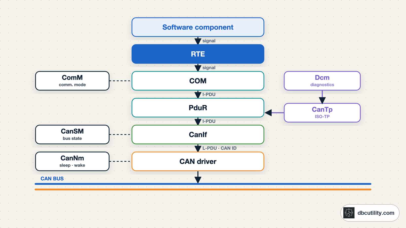
In short
In AUTOSAR, a software component writes a signal, COM packs it into an I-PDU, the PDU router passes it on, CanIf turns it into a CAN frame with an ID, and the CAN driver sends it. Diagnostics take a side path through CanTp, and CanSM and CanNm manage when the bus is awake.
Best for: CAN, integration, test, and embedded engineers who work with AUTOSAR ECUs, ARXML, or DBC files generated from AUTOSAR
You see a frame 0x2A0 on the bus every 20 ms, and the ARXML says it is a PDU called BrakeStatus_PDU from the brake ECU. Between the brake function writing a value and that frame appearing, the value passes through several AUTOSAR modules. Knowing which module does what tells you where to look when a signal is wrong, late, or missing.
This guide covers the Classic Platform, which runs on almost every CAN-connected ECU. For the bigger picture, start with what AUTOSAR is.
The stack at a glance
  Software component (SWC)
      |  Rte_Write / Rte_Read
      v
RTE
      |  signals
      v
COM  ----------------------  Dcm (diagnostics)
      |  I-PDUs                  |  diagnostic messages
      v                          v
PduR (PDU router)  <------>  CanTp (ISO-TP)
      |  I-PDUs                  |  N-PDUs
      v                          v
CanIf (CAN interface)  <---------+
      |  L-PDUs (frames)
      v
Can (CAN driver)   CanTrcv (transceiver driver)
      |
CAN controller and transceiver  ->  CAN bus

Alongside: ComM, CanSM (bus state), CanNm (network management), BswM, EcuM
Three kinds of PDU
AUTOSAR names data units by layer. You will see these names in ARXML and in tool menus:
| Name | Layer | What it is | Typical owner |
|---|---|---|---|
| I-PDU | Interaction layer | A group of signals, the payload of a message | COM |
| N-PDU | Network layer | A segment of a longer message | CanTp |
| L-PDU | Data link layer | A CAN frame: ID, length, and data | CanIf and the CAN driver |
In the simplest case, one I-PDU fills one CAN frame, so the I-PDU and the L-PDU carry the same bytes. They differ when a frame is segmented (diagnostics) or when several I-PDUs share one CAN FD frame.
What each module does
COM turns signals into I-PDUs and back. It packs each signal at its start position with its byte order, keeps initial values, and decides when to send: periodically, on change, or both. On receive, it unpacks signals, checks for timeouts, and can substitute a default value when a message stops arriving.
PduR (PDU Router) passes I-PDUs between modules without changing them. It routes COM PDUs to CanIf, diagnostic PDUs to CanTp, and, in a gateway ECU, PDUs from one bus to another.
CanIf (CAN Interface) connects the upper layers to one or more CAN controllers. It maps each PDU to a CAN ID and a hardware buffer for sending, and filters received frames by ID and checks their length before passing them up. It also passes controller mode requests and transmit and receive confirmations.
Can (CAN driver) is part of the MCAL. It programs the CAN controller in the microcontroller: bit timing, hardware mailboxes, and interrupts. It is the only module that touches CAN registers.
CanTrcv (transceiver driver) controls the CAN transceiver chip, for example switching it between normal, standby, and sleep modes, and reporting wake-up events.
CanTp (CAN transport protocol) implements ISO 15765-2 (ISO-TP). It splits messages longer than one frame into N-PDUs and reassembles them. Diagnostics (UDS through Dcm) use it.
CanSM (CAN state manager) brings the CAN network up and down when ComM asks, and handles bus-off recovery: after a bus-off it restarts the controller and reports the error.
CanNm (CAN network management) coordinates sleep and wake-up between ECUs with NM messages, so a network goes to sleep only when every ECU is ready.
ComM, BswM, and EcuM decide when communication is needed at all, based on the ECU's state and requests from applications.
Following one signal out
Say a brake SWC writes BrakePedalPressed = 1:
- The SWC calls an RTE function such as
Rte_Write_BrakePedal_Pressed(1). - The RTE passes the value to COM.
- COM writes the bit into the
BrakeStatus_PDUbuffer at its configured position. If the PDU is periodic, COM sends it on the next 20 ms cycle; if the signal is configured to trigger a send, COM sends it now. - PduR forwards the I-PDU to CanIf.
- CanIf looks up the CAN ID (
0x2A0) and the hardware buffer for that PDU and calls the CAN driver. - The CAN driver loads the frame into a mailbox, and the controller sends it when it wins arbitration.
- When the frame has been sent, a confirmation travels back up to COM, which can use it for deadline monitoring.
On another ECU, the frame goes up the same path in reverse: the CAN driver receives it, CanIf accepts the ID and checks the length, PduR routes it to COM, COM unpacks BrakePedalPressed, and the receiving SWC reads it through the RTE.
Diagnostics take a side path
A UDS request is longer than one CAN frame when it carries data, so it does not go through COM:
Tester -> CAN -> Can -> CanIf -> CanTp -> PduR -> DcmCanTp reassembles the ISO-TP frames, and the diagnostic communication manager (Dcm) handles the UDS service. Our UDS overview explains the services themselves.
Where the configuration comes from
Every value in the steps above is configured in ARXML. A CAN engineer usually meets these elements of the system description:
| ARXML element | What it defines | Closest DBC idea |
|---|---|---|
CAN-CLUSTER | One CAN network and its baud rate | The network the DBC describes |
CAN-FRAME and CAN-FRAME-TRIGGERING | Frame length and CAN ID | BO_ message ID and length |
I-SIGNAL-I-PDU | The PDU that carries signals, with timing | The message's payload and cycle time attribute |
I-SIGNAL-TO-I-PDU-MAPPING | Each signal's start position and byte order | SG_ start bit and @1/@0 |
I-SIGNAL and COMPU-METHOD | Signal length, initial value, and scaling | SG_ length, scale, offset, and start value |
So a DBC message is roughly a CAN frame plus the I-PDU inside it, and a DBC signal is an I-signal plus its position in the PDU. Things that have no DBC equivalent, such as PDU timeouts or several PDUs in one frame, are lost or flattened when you export a DBC. See what to check after converting ARXML to DBC.
AUTOSAR features you will see on the bus
These show up as extra signals or bytes when you decode an AUTOSAR ECU's frames:
- Update bits. One bit per signal or signal group that says whether the value was freshly written.
- I-PDU multiplexing. One CAN ID carries different layouts selected by a selector field, like a multiplexed DBC message.
- Container PDUs. On CAN FD, several I-PDUs can be packed into one frame, each with a small header.
- End-to-end protection (E2E). A counter and a CRC added to safety-relevant data so the receiver can detect lost, repeated, or corrupted messages.
- Secure onboard communication (SecOC). A message authentication code and freshness value added to the PDU.
J1939 in AUTOSAR
AUTOSAR also has modules for SAE J1939, used in trucks and machines:
- J1939Tp for the J1939 transport protocol (BAM and RTS/CTS).
- J1939Nm for address claiming.
- J1939Rm for requests and acknowledgements.
- J1939Dcm for J1939 diagnostic messages such as DM1.
They sit in the same place as CanTp, CanNm, and Dcm, on top of CanIf. Our guides to the J1939 transport protocol, address claiming, and DM1 fault codes explain what goes over the wire.
Debugging with the stack in mind
| Symptom on the bus | Where to look |
|---|---|
| Frame never appears | ComM/CanSM never started the network, or the PDU is not routed in PduR |
| Frame appears but a signal is stuck at its initial value | The SWC never writes it, or the RTE connection is missing |
| Signal value is wrong but changes | Start position, byte order, or scaling in the ARXML (and in the DBC generated from it) |
| Receiver uses a default value | COM timeout on the receiving ECU: the frame is late, or its ID or length does not match |
| ECU stops sending after errors | Bus-off; CanSM recovery settings and the physical layer |
| Diagnostics time out but normal frames work | CanTp configuration: addressing, timing, or block size |
Frequently asked questions
What is the difference between CanIf and the CAN driver in AUTOSAR?
The CAN driver is part of the MCAL and talks to the CAN controller's registers on one microcontroller. CanIf sits above it, maps PDUs to CAN IDs, filters received frames, and gives the upper layers one interface regardless of which CAN controllers the ECU has.
What is an I-PDU in AUTOSAR?
An I-PDU (interaction layer PDU) is a group of signals packed by COM. In the simplest case it is the data of one CAN frame. The CAN frame itself, with its ID, is called an L-PDU.
How does AUTOSAR handle messages longer than 8 bytes on CAN?
Diagnostic and other long messages go through CanTp, which implements ISO-TP and splits them into several frames. On CAN FD, frames can carry up to 64 bytes, and container PDUs can pack several I-PDUs into one frame. J1939 networks use J1939Tp instead of CanTp.
References
DBC Utility
One desktop app for DBC files and CAN recordings.
One-time $34 · Windows & Linux · Files stay on your computer