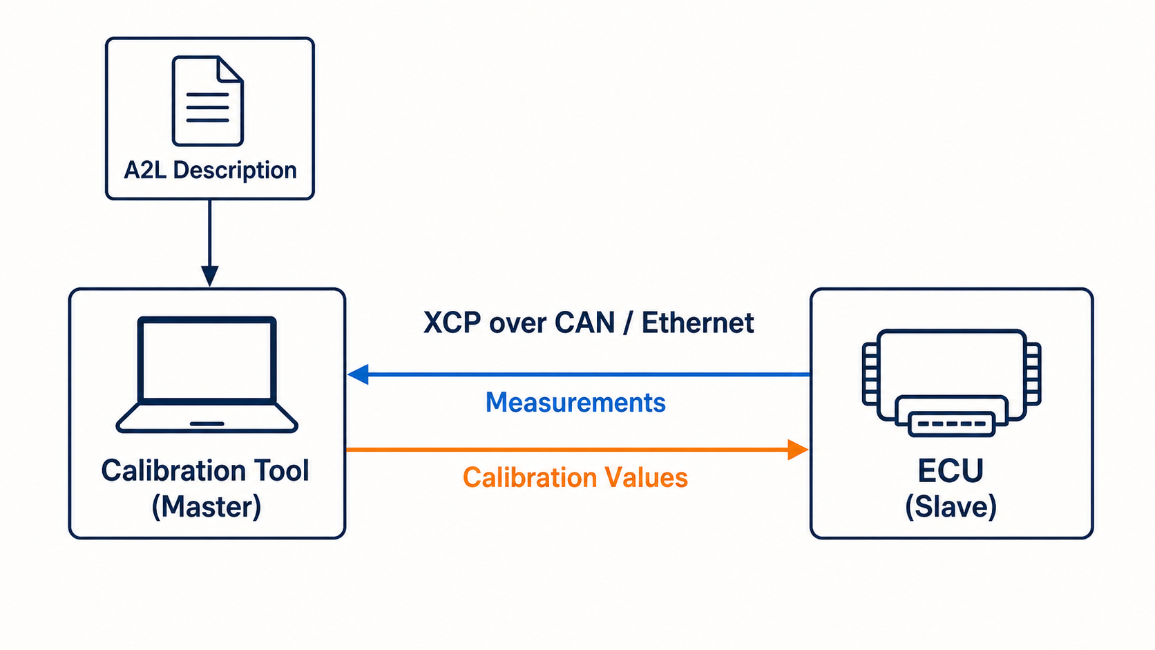
XCP in simple words
XCP is a protocol used by engineering tools to measure and calibrate values inside an ECU while the ECU software is running.
XCP stands for Universal Measurement and Calibration Protocol. It is standardized by ASAM.
A typical setup has:
- one XCP master, usually a calibration or test application
- one XCP slave, usually the ECU
- a transport such as CAN or Ethernet
- an A2L file that describes variables, parameters, addresses, and conversions
Why engineers use XCP
During ECU development, engineers need to see more than normal CAN signals. They may need to read an internal control value that is not broadcast on the vehicle network or adjust a calibration parameter without rebuilding the firmware.
XCP is commonly used for:
- reading internal measurement variables
- changing calibration parameters
- collecting high-rate measurement data
- stimulating selected variables when supported
- ECU programming in supported implementations
- development-time debugging workflows
XCP is normally a development and calibration protocol. It should be protected or disabled appropriately in production systems according to the project's security design.
XCP master and slave
XCP uses a master-slave model.
Calibration tool (master)
  |
  | XCP commands and data
  v
ECU (slave)
The master sends commands. The ECU responds. For data acquisition, the ECU can also send measurement packets configured by the master.
Common command ideas include:
- connect
- get status
- set memory transfer address
- upload data from ECU memory
- download data to ECU memory
- configure data acquisition lists
The exact supported commands depend on the ECU's XCP implementation and resource protection.
XCP is transport-independent
The X in XCP reflects that the protocol can use different transports.
Common choices include:
- XCP on CAN
- XCP on CAN FD
- XCP on Ethernet using UDP or TCP
- XCP on USB
- XCP on serial interfaces
The base protocol describes the command and data behavior. Transport-layer specifications describe how those packets are carried on each network.
XCP on CAN is familiar and widely supported, but classical CAN has a small payload and limited bandwidth. XCP on Ethernet is often chosen when measurement throughput is more important.
What is an A2L file?
An A2L file is the description that gives names and meaning to ECU memory.
It can describe:
- measurement variable names
- calibration parameter names
- memory addresses
- data types
- byte order
- units
- conversion formulas
- valid ranges
- XCP connection information
Without an A2L file, a tool may still access a raw address if the address is known. With the correct A2L, an engineer can choose a name such as EngineSpeed_Internal instead of manually entering an address and data type.
The A2L must match the ECU software build. If firmware changes move a variable, an old A2L can point to the wrong address.
XCP measurement flow
A simplified measurement workflow is:
- Connect to the XCP slave.
- Check supported resources and packet sizes.
- Load the A2L that matches the firmware.
- Select measurement variables.
- Configure data acquisition lists and events.
- Start acquisition.
- Record and analyze the samples.
- Stop acquisition and disconnect.
For one small value, a master can also use direct memory upload commands. DAQ lists are better for repeated, time-related measurement.
XCP calibration flow
A simplified calibration workflow is:
- Connect to the ECU.
- Unlock the calibration resource if required.
- Read the current parameter value.
- Write the approved test value.
- Observe the ECU behavior.
- Restore or save the final calibration using the project's defined process.
Never write an unknown address. Use a controlled test setup, the matching A2L, valid ranges, and the project's safety process.
XCP vs CCP
CCP is an older CAN-specific calibration protocol. XCP followed it with a transport-independent design.
CCP -> designed specifically for CAN
XCP -> base protocol with several possible transports
Existing projects may still use CCP, but new integrations often discuss XCP.
XCP vs UDS
XCP and UDS can both communicate with an ECU, but they have different main jobs.
| XCP | UDS |
|---|---|
| Measurement and calibration | Vehicle diagnostics and service functions |
| Direct access to described ECU variables and parameters | Service-based requests such as sessions, DIDs, DTCs, routines, and flashing |
| Common in development and calibration | Common in development, manufacturing, and service diagnostics |
| Uses A2L descriptions | Often uses diagnostic descriptions such as ODX or project data |
An ECU project can support both protocols.
XCP vs normal CAN signals
A normal CAN signal is usually packed into a frame that the ECU broadcasts to other nodes. XCP can access selected internal values that are not part of the normal network communication.
DBC and A2L also have different jobs:
DBC -> describes CAN messages and signals
A2L -> describes ECU measurements, calibrations, memory access, and conversions
What you need to try XCP
- an ECU or simulator with an XCP slave
- the correct transport settings
- the master transmit and receive IDs for XCP on CAN
- a matching bitrate
- an XCP tool or library
- ideally, the matching A2L file
- permission to perform measurement or calibration on the target
A random CAN connection is not enough. The ECU must contain and enable an XCP slave.
The simple summary
XCP connects an engineering tool to an ECU for measurement and calibration. The tool is the master, the ECU is the slave, and an A2L file explains the available values. XCP can run over CAN, Ethernet, and other transports, which makes it different from the older CAN-only CCP protocol.